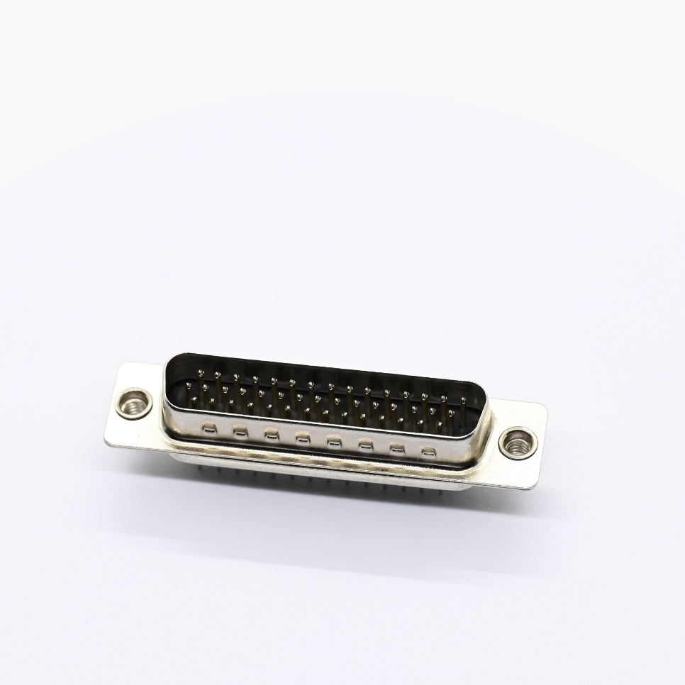
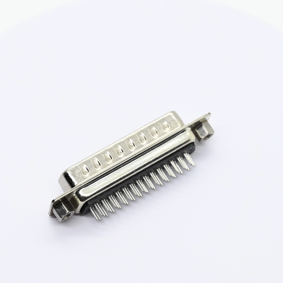
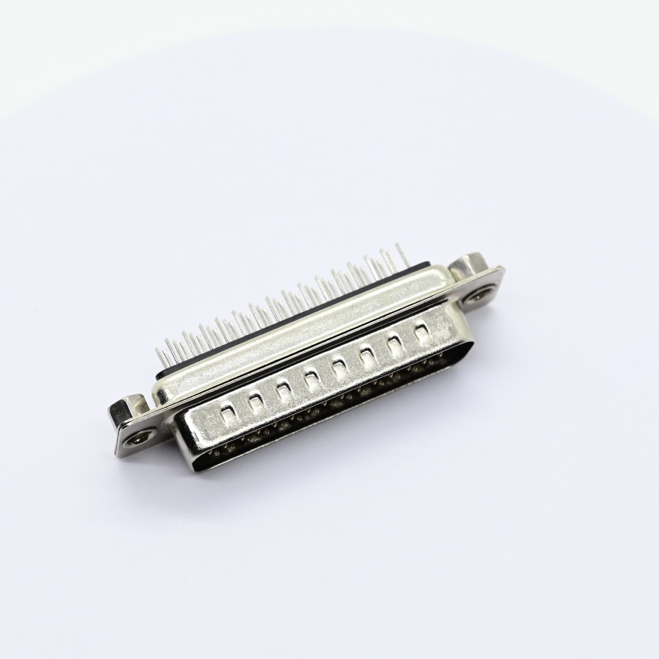
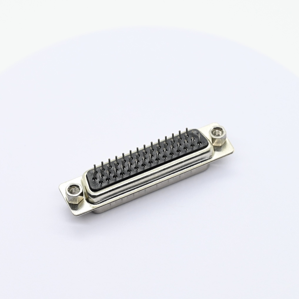
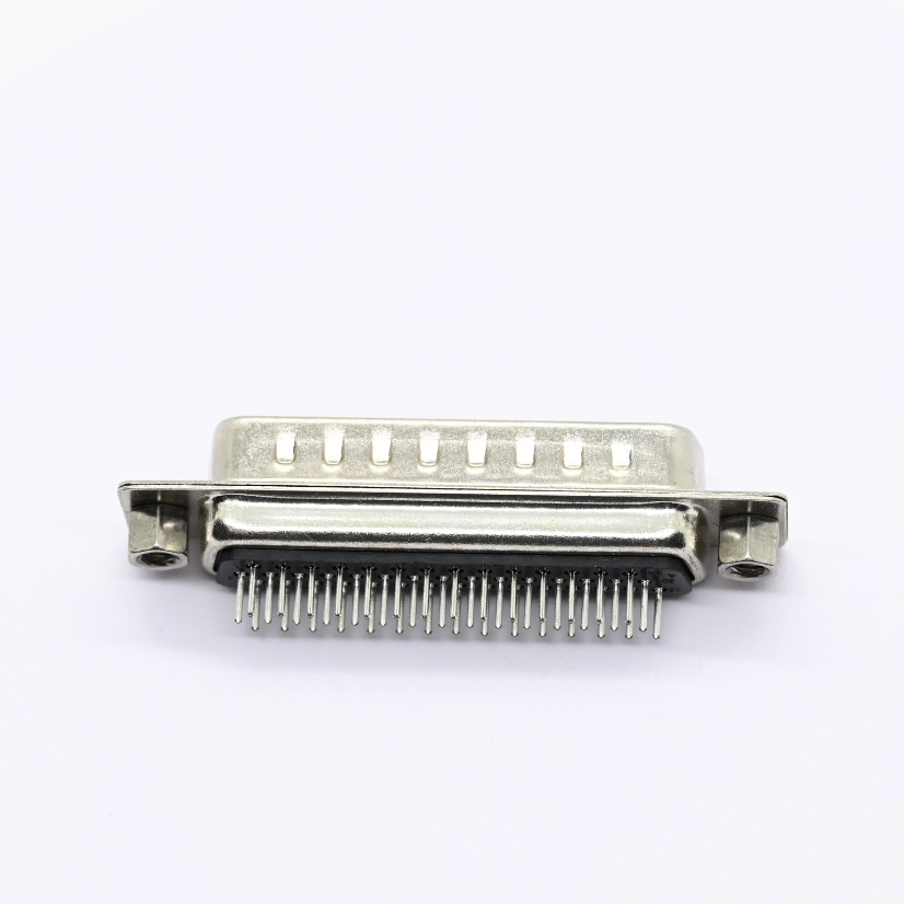
1. Stamped D SUB Contact provides reliable signal transmission with stable electrical performance for three‑row D‑SUB male connectors.
2. PBT GF SUB Housing delivers good flame retardancy and mechanical strength for long‑term PCB assembly environments.
3. Nickel Plated Shell offers effective shielding and corrosion resistance to protect inner contacts from external interference.
Detailed Specifications:
1. Electrical Specifications
1.1 Rated current: 5A
1.2 Maximum contact resistance: 20 milliohms
1.3 Withstanding voltage: 500V AC for 1 minute
1.4 Minimum insulation resistance: 1000 Megohms
1.5 Operating temperature range: -55°C to +105°C
2. Mechanical Specifications
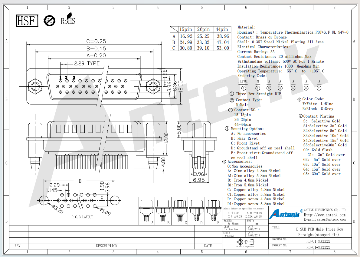
2.1 Contact configurations: 15 pin, 26 pin, 44 pin
2.2 Mounting options: No accessory, front rivet, rear rivet, ground stand‑off, front rivet plus ground stand‑off
2.3 Terminal type: Three row straight DIP stamped pin
2.4 Dimensional tolerance: X.XX ±0.20 mm, shtur ±0.15 mm, C ±0.25 mm
3. Material & Surface Finishing
3.1 Housing material: PBT plus glass fiber thermoplastic, UL94V‑0 flame retardant
3.2 Contact material: Brass or bronze
3.3 Shell material: 0.35T steel with full area nickel plating
3.4 Housing color options: White, Blue, Black, Grey
3.5 Contact plating options: Gold flash, various thickness full gold plating and selective gold plating
4. Dimensional Parameters (Unit:mm)
4.1 Overall length dimensions vary for 15pin,26pin,44pin: 16.92‑53.00 as per drawing
4.2 Compatible stand‑off height options: 4.8mm and 5.8mm
4.3 Follow official PCB layout drawing for through‑hole soldering footprint
5. Compliance Standard
5.1 Compliance: RoHS and HSF compliant
6. Application Scenarios
6.1 Industrial control panels and communication hardware
6.2 Power supply units and digital household appliances
6.3 Computer peripherals, automotive electronics and precision measuring instruments
7. Operation & Storage Precautions
7.1 Select correct pin count, shell mounting style, housing color and contact plating according to project requirements
7.2 Adopt recommended PCB layout for DIP through‑hole soldering process
7.3 Control soldering temperature to prevent thermal damage to PBT plus glass fiber housing
7.4 Do not exceed 5 Amp maximum rated current during working condition
7.5 Store finished connectors in dry sealed packages to avoid oxidation of brass and steel components
FAQ
Q: How many packaging do you have?
A: We have five packages including PE bag, hand bag, zip lock bag, colorful box and white box currently.
Q: Can you do our own packaging?
A: Yes, you just provide the package design and we will produce what you want. We also have the professional designer can help you do the packaging design.
Q: How many different types of products your company manufactures?
A: Now we have more than 1,000 products. We have a strong advantage of OEM, just give us the actual products or your idea that you want, we will manufacture for you.
Product Drawing: