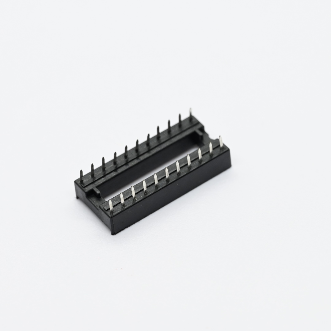
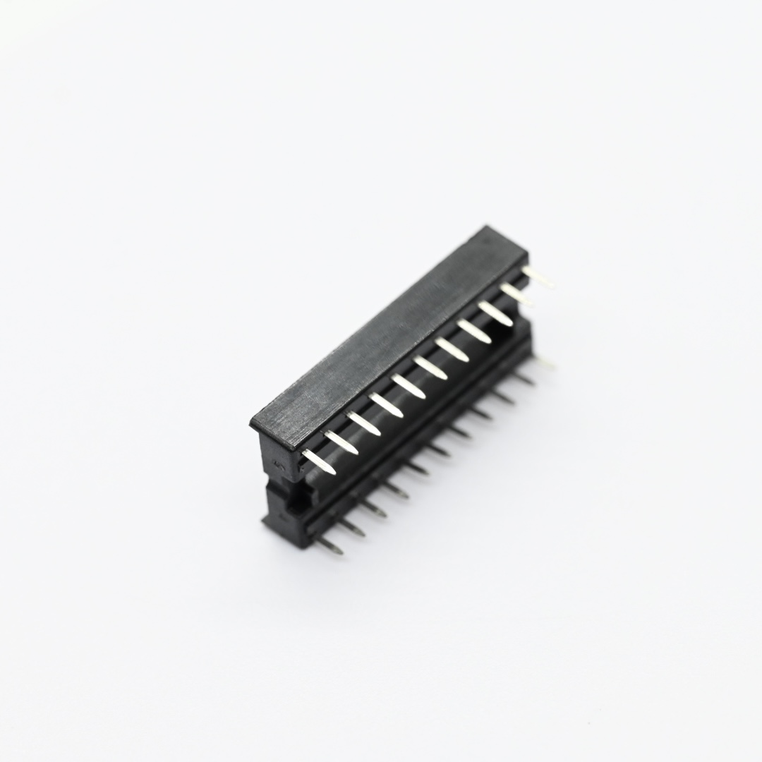
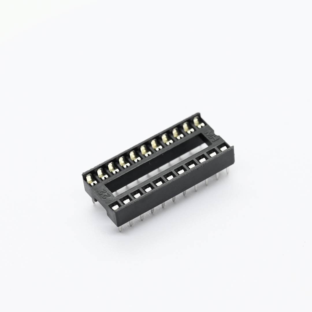
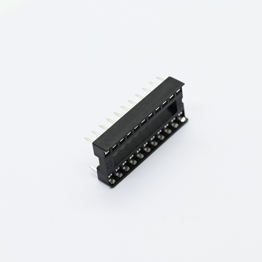
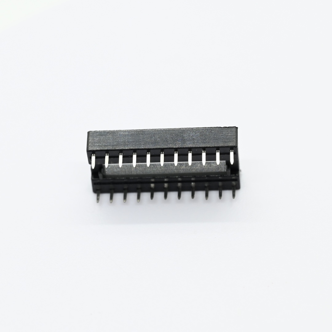
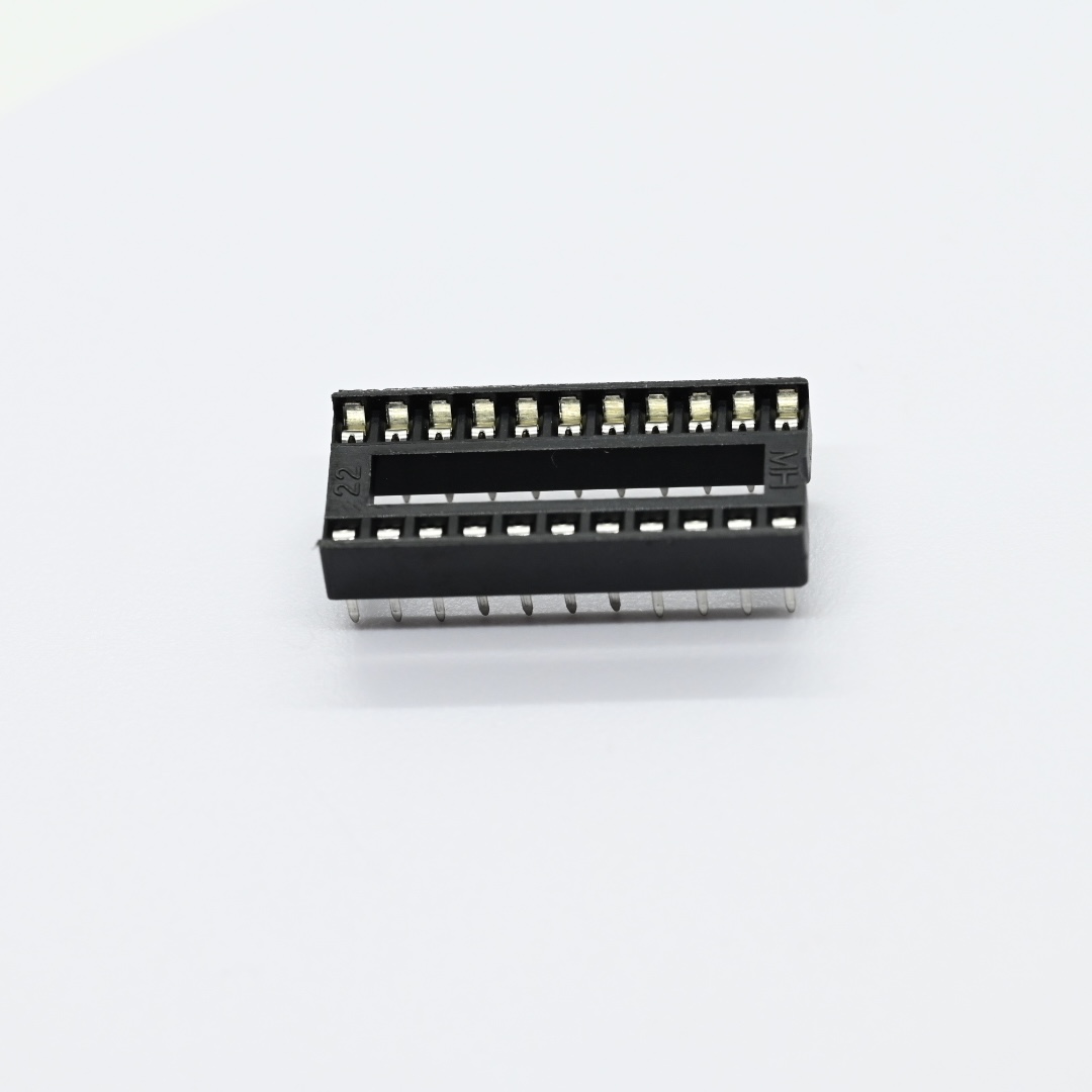
1. Stamped DIP Socket adopts precision stamped contact structure to offer stable signal transmission for various integrated chip applications.
2. Phosphor Bronze IC Socket uses high performance phosphor bronze contacts to maintain stable spring force after repeated plug and unplug operations.
3. PBT GF IC Receptacle applies PBT plus glass fiber housing material to deliver excellent mechanical strength and flame retardant performance.
Detailed Specifications:
1. Mechanical Specifications
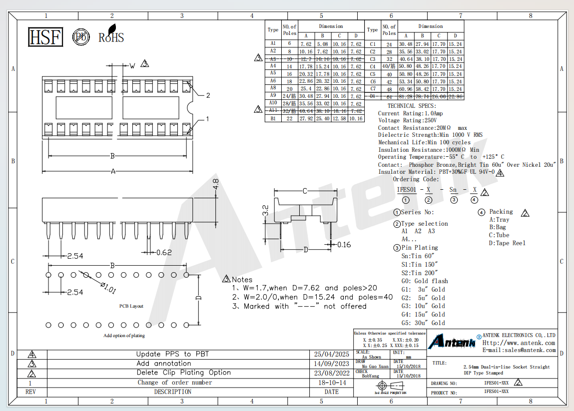
1.1 Product type: Stamped straight dual in‑line DIP IC socket
1.2 Measurement unit: millimeter
1.3 Key dimension: 2.54 millimeter pitch, pole options from 6 pins up to 64 pins. General drawing tolerances X.XX ±0.20, X.XXX ±0.15. Refer to official engineering drawing for complete dimension tables and PCB footprint reference data.
1.4 Contact plating options: 60u tin,150u tin,200u tin, gold flash, 3u gold,5u gold,10u gold,15u gold,30u gold
1.5 Available packaging form: Tray, bag, tube, tape and reel
1.6 CTA: Contact our engineering team to obtain complete dimension drawings and PCB layout files for your hardware design validation.
2. Material Construction
2.1 Insulator housing: PBT plus 30 percent glass fiber with UL94V 0 flame retardant grade
2.2 Contact terminal: Phosphor bronze material, 20u nickel base layer, default 60u bright tin surface plating
3. Electrical & Performance Parameters
3.1 Rated current: 1.0 Amp
3.2 Maximum contact resistance: 20 milliohms
3.3 Dielectric strength: Minimum 1000V RMS
3.4 Minimum insulation resistance: 1000 megaohms
3.5 Mechanical life: Minimum 100 insertion and removal cycles
3.6 Operating temperature range: ‑55 degree Celsius to +125 degree Celsius
4. Usage Method
4.1 Assembly mode: Through hole DIP soldering onto printed circuit boards
4.2 Operation tip: Select proper pole count and contact plating according to integrated chip and actual circuit requirements
5. Application Scenarios
5.1 Industrial control circuit boards
5.2 Instrument and meter equipment
5.3 Consumer electronic products
5.4 Microcontroller development hardware
6. Operation & Storage Precautions
6.1 Follow official drawing tolerance standards for PCB layout design
6.2 Avoid excessive plugging force to prevent phosphor bronze contact spring deformation
6.3 Store finished goods under dry environment to prevent oxidation of tin or gold plated contact surfaces
6.4 Confirm pole number plating specification and dimension parameters before mechanical and circuit design
6.5 CTA: Submit your pin count plating and packaging requirements, we can provide free sample evaluation and professional technical consultation.