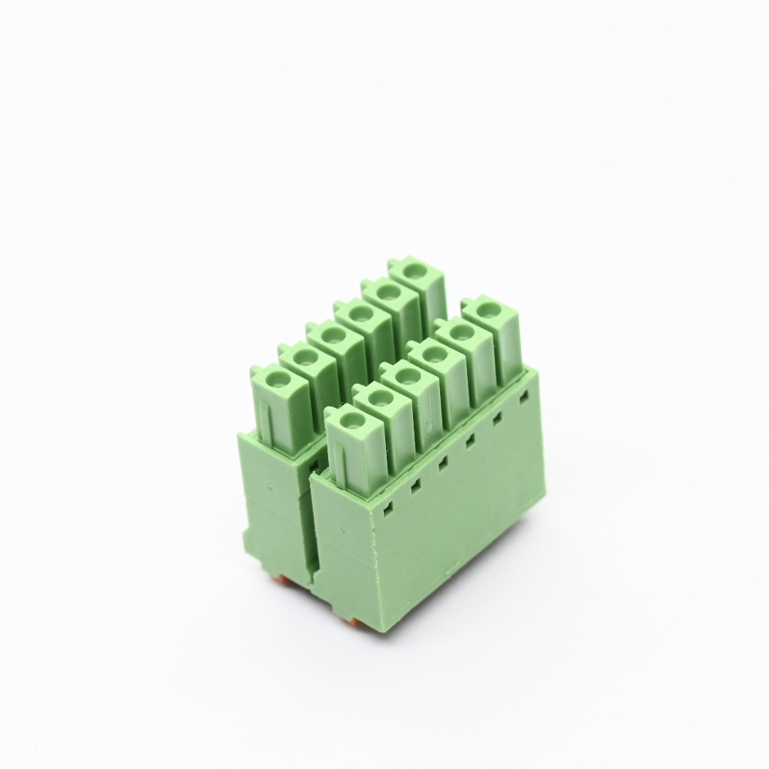
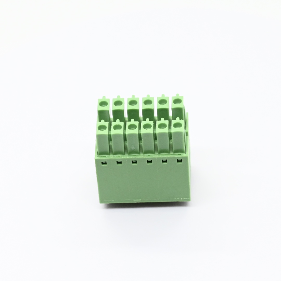
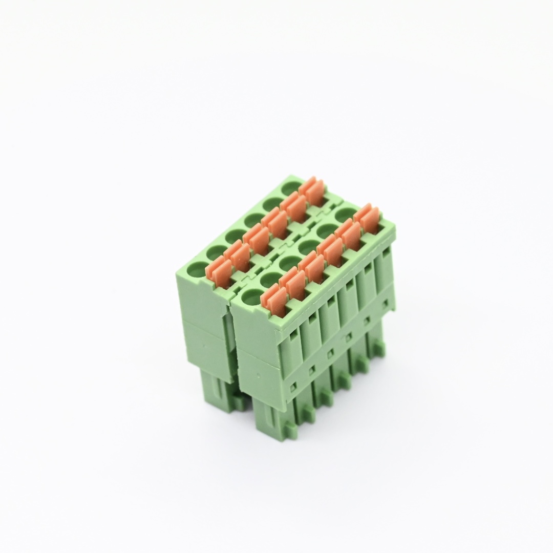
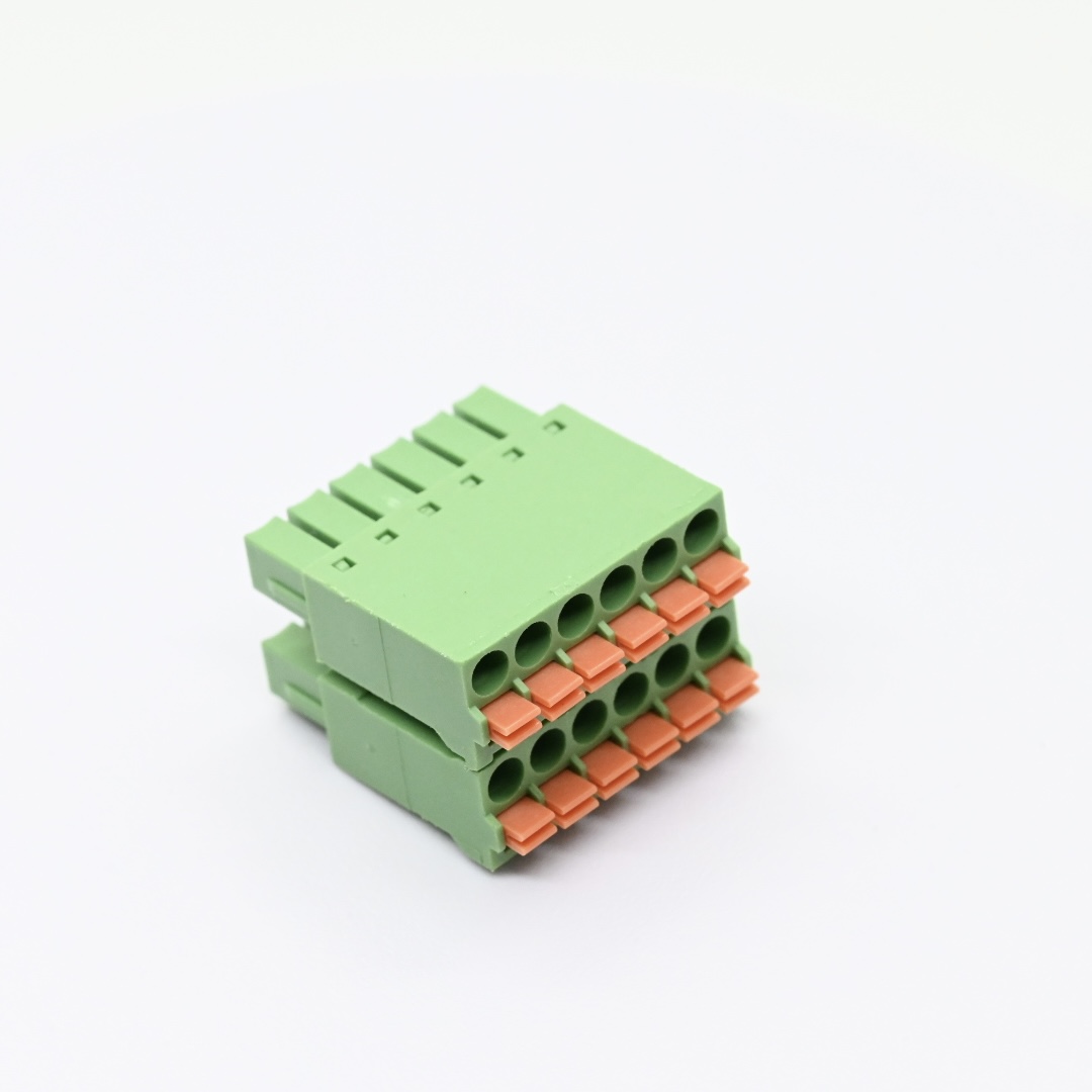
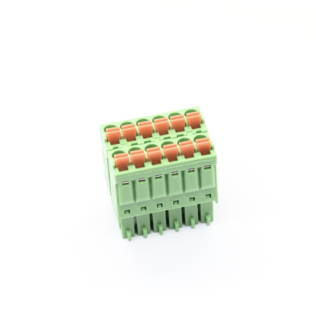
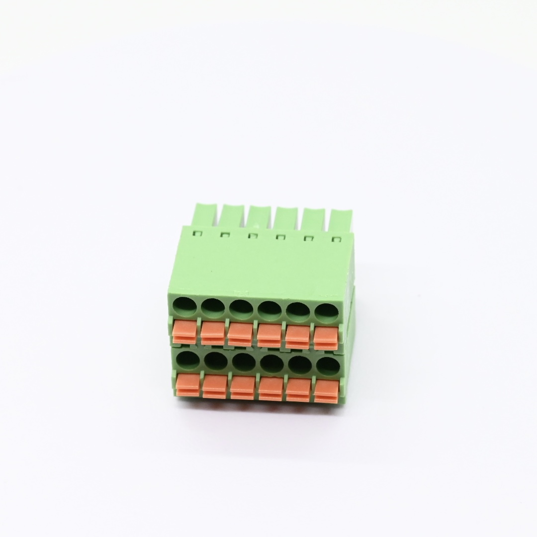
1. Screwless Terminal Block utilizes stainless steel spring clamp to achieve quick and reliable wire connection without extra screw tightening operations.
2. PA Insulated Terminal Block adopts polyamide housing with UL94V 0 flame retardant rating to provide safe insulation protection for circuit systems.
3. Stainless Spring Terminal delivers stable clamping force for wires and maintains long term performance under wide operating temperature range.
Detailed Specifications:
1. Mechanical Specifications
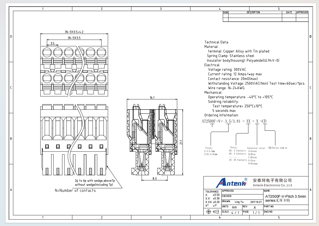
1.1 Product type: 3.5 millimeter pitch no ear latch spring clamp terminal block
1.2 Measurement unit: millimeter
1.3 Key dimension: 3.5 millimeter pitch, pole quantity ranges from 2 poles up to 16 poles. Units from 2 pole to 6 pole are equipped with wedge structure, 7 pole and above remove wedge. Refer to official engineering drawing for complete dimension tables and PCB footprint reference data.
1.4 Applicable wire range: 16‑24 AWG
1.5 Available housing color: Green, Blue, Gray, Black
1.6 CTA: Contact our engineering team to obtain complete dimension drawings and PCB layout files for your hardware design validation.
2. Material Construction
2.1 Insulator housing: Polyamide material with UL94V 0 flame retardant grade
2.2 Contact terminal: Tin plated copper alloy
2.3 Spring clamp component: Stainless steel
3. Electrical & Performance Parameters
3.1 Rated voltage: 300V AC
3.2 Rated current: 12 Amp per way maximum
3.3 Maximum contact resistance: 20 milliohms
3.4 Dielectric withstand: 2500V AC for one minute
3.5 Operating temperature range: minus 40 degree Celsius to plus 105 degree Celsius
3.6 Soldering reliability: withstand 250 degree Celsius plus minus 10 degree Celsius for maximum 5 seconds
4. Usage Method
4.1 Assembly mode: Soldering onto printed circuit boards
4.2 Operation tip: Select proper pole count, housing color and confirm wire gauge before wiring operation
5. Application Scenarios
5.1 Industrial control devices
5.2 Automation equipment assemblies
5.3 Instrument and meter products
5.4 General wire to board interconnection systems
6. Operation & Storage Precautions
6.1 Follow drawing tolerance standards strictly for PCB layout design
6.2 Use wire within specified AWG range to avoid poor contact or spring damage
6.3 Keep products in dry storage environment to prevent oxidation of tin plated terminals
6.4 Confirm pole number and housing specifications before mechanical and circuit design
6.5 CTA: Submit your pole count color and wire application requirements, we can provide free sample evaluation and professional technical consultation.