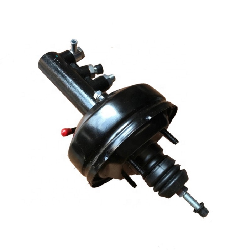
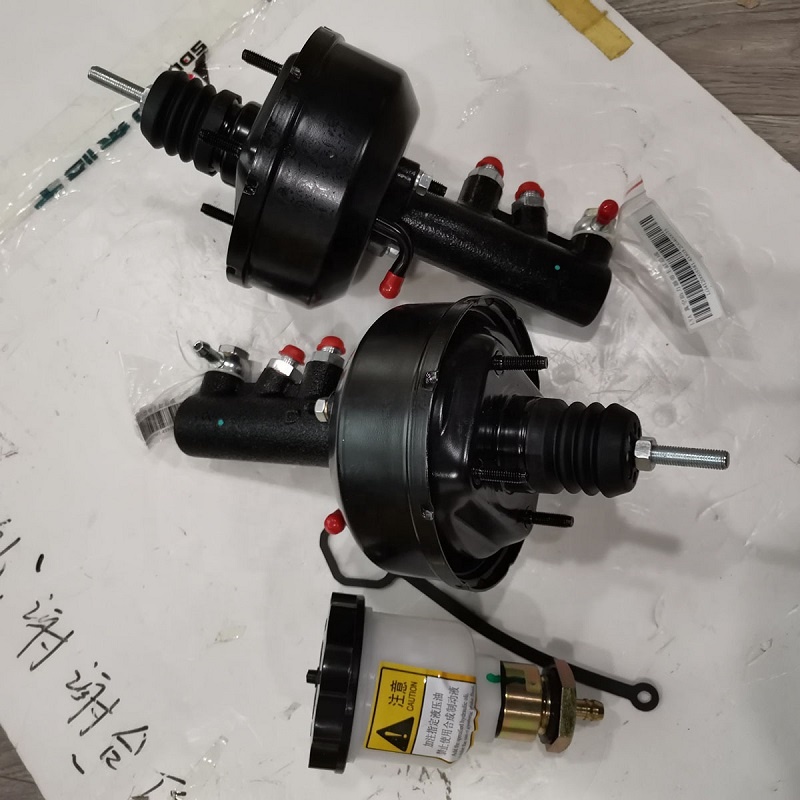
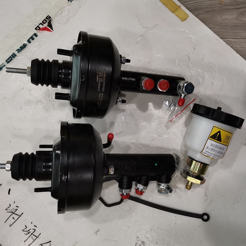
Basic Structure
The vacuum servo air chamber is composed of front and rear housings 1 and 19, and a servo air chamber diaphragm 20 is sandwiched between the two, which divides the servo air chamber into front and rear chambers. The front chamber leads to the engine intake manifold (ie, the vacuum source) through the vacuum check valve 9, and the outside air enters the rear chamber of the servo air chamber after being filtered by the filter ring 11 and the felt filter ring 14. A control valve 6 is installed in the hub barrel of the rear cavity diaphragm seat 8 . The control valve is composed of an air valve 10 and a vacuum valve 9. The structural diagram is partially enlarged as shown in Figures 2b and c. The air valve and the control valve push rod 12 are fixed together, and the control valve push rod is connected to the brake by the adjusting fork 13. Pedal mechanism connection. There are channels A and B on the diaphragm seat 8 of the servo air chamber, the channel A is used to communicate with the front chamber of the servo air chamber and the control valve, and the channel B is used to communicate with the rear chamber of the servo air chamber and the control valve. The thrust generated by the vacuum servo air chamber, like the pedal force, acts directly on the push rod 2 of the brake master cylinder. When the vacuum booster does not work, the air valve 10 and the control valve push rod 12 leave the rubber reaction plate 7 under the action of the control valve push rod spring 15 and are at the right end limit position, and make the vacuum valve 9 leave the diaphragm seat 8. The valve seat, that is, the vacuum valve is in the open state. And the vacuum valve is pressed on the air valve by the valve spring 16, that is, the air valve is in a closed state. At this time, the front and rear cavities of the servo air chamber communicate with each other and are isolated from the atmosphere. When the engine is working, a certain degree of vacuum can be generated in the front and rear chambers. When braking, step on the brake pedal, the control force from the pedal mechanism pushes the control valve push rod 12 and the control valve plunger 18 to move forward, after eliminating the gap between the plunger and the rubber reaction disc 7, continue to push The brake master cylinder push rod 2, the brake fluid in the master cylinder flows into the brake wheel cylinder with a certain pressure, and this force is given by the brake pedal mechanism. At the same time, under the action of the valve spring 16, the vacuum valve 9 also moves forward until it is pressed against the valve seat of the diaphragm seat, thereby isolating the channels A and B, that is, the front chamber of the servo air chamber and the valve seat of the diaphragm seat. The back cavity is isolated, and then the air valve is opened from the vacuum valve, and the air is filled into the back cavity of the servo air chamber through the filter ring 11, the felt filter ring 14, the opening of the air valve and the channel B. With the filling of air, a pressure difference occurs on both sides of the servo air chamber diaphragm 20 to generate thrust, which pushes the brake master cylinder push rod 2 to move forward through the diaphragm seat 8 and the rubber reaction disc 7. This force given by the pressure difference. At this time, the force on the push rod of the master cylinder is the sum of the pedal force and the thrust of the reaction disc of the servo air chamber, so that the output pressure of the master cylinder is doubled. When the brake is released, the control valve push rod spring 15 moves the control valve push rod and the air valve to the right, and the vacuum valve leaves the valve seat on the diaphragm seat and opens. The front and rear cavities of the servo air chamber are connected and both are in a vacuum state. The diaphragm seat and diaphragm return to their original position under the action of the diaphragm return spring, and the brake master cylinder releases the braking effect. If the vacuum booster fails or there is no vacuum in the vacuum line, the control valve push rod will directly push the diaphragm seat and the brake master cylinder push rod to move through the air valve, so that the brake master cylinder generates braking pressure, but acts on the pedal. force to increase.